
Note that I mostly build on what other people researched and just put those results together however it is nice to have everything in one place. All credits go to the various authors I link to except for the glue in between (i.e. Atmel Studio part). So this will be mainly a starting point to the various sites.
This is a lot of text and I probably will spice it up a bit in the future with pictures of scantily dressed women, I mean boring diagrams and photos of ATMega328p’s.
Ok, with that out of the way let’s start. First off what do we need:
- Raspberry Pi
- ATMega328P
- Breadboard
- Wires to connect stuff
- Optional 5 * 1K resistors (to protect your Raspberry Pi).
- And of course an OLED display
- Windows (I do it on windows you have to improvise for Linux however most or almost all tutorial are for Linux so you should be OK there).
- Atmel Studio
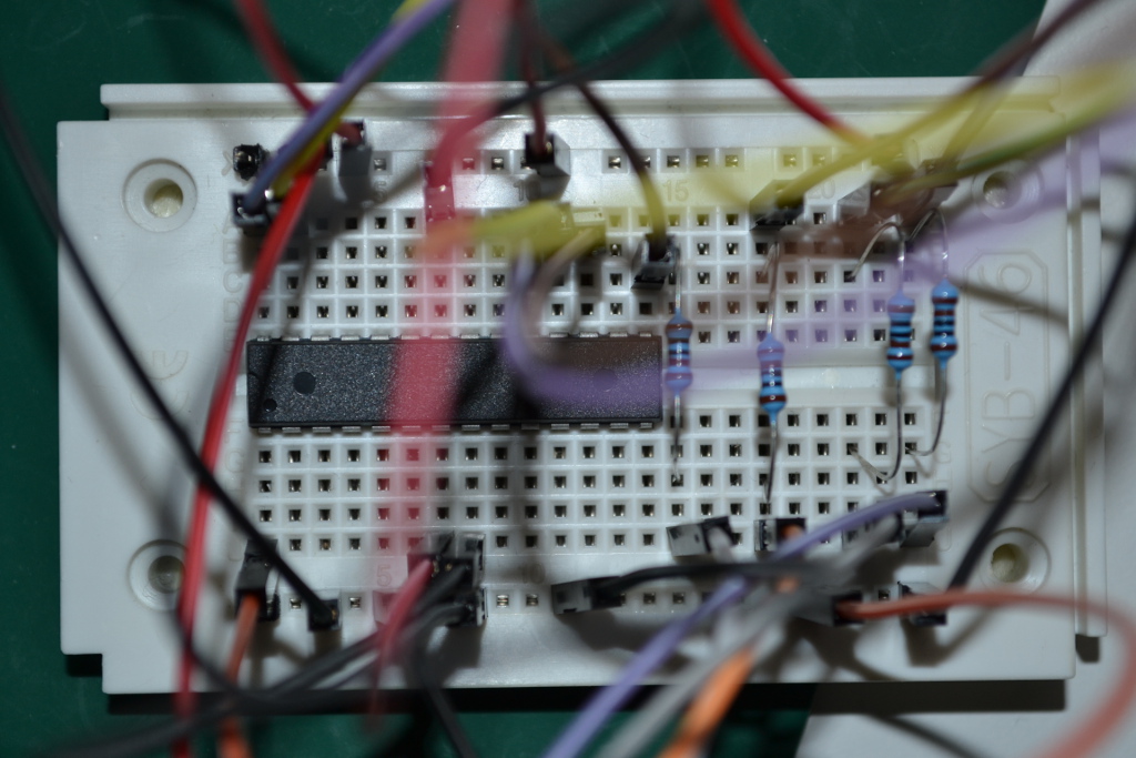
ATMega328P’s are fond of breadboards and easily trapped in one. No worries though, I added a life support system to feed it.
Setting up and connecting the ATMega328P to your RPi
For that go to this site BUT instead of using the pin assignment for the ATTiny go to this site. Admire the ATMega328P with its many pins for a while and in the mean time I am going to get a cup of coffee while you lookup and connect the corresponding pins for the ATMega328P.
So you’re finally back (I drank coffee, cleaned the house and destroyed some IC’s with static electricity in the mean time but that’s OK).
Atmel Studio
We will be using Atmel Studio to compile stuff and then scp the resulting binary to your Raspberry.
- Download Atmel Studio. You probably have to supply your email and you get some nice ‘Maker’ info from Atmel. Your are now an official ‘Maker’ 🙂
- Install Atmel Studio. This is Visual Studio under the hood so if you are familiar with it you feel right at home. If not and haven’t used any IDE before, you are probably looking at a confusing quagmire of User Interface Elements. Don’t worry though, I’ve got you covered, even if you haven’t got the remotest clue what you’re doing or even what we’re trying to accomplish here in the first place.
- Start it and after a while you arrive at the welcome page.
- Select ‘New Project…
- Select ‘GCC Executable Project’
- Give it an original name (like OLED).
- Now there is a device selection window (may not be the top window). Click on it and select ATMega328P
- You are in your little project but as good cut & paste developers we are not going to program, yet…
- Instead, of writing the lower layers, I downloaded the UG8 library for AVR and build on the Herculean job other developers have done.
- Once downloaded unzip it and descent into the ug8lib/src dir.
- In another window go into your Atmel studio source dir (one deeper than where your *.atsln file is). So if you named the project OLED you should select that dir twice to get there.
- Select all ‘.c’ and ‘.h’ files and copy them to from ug8lib/src and copy them to the second window.
- Now in Atmel studio the right pane should contain ‘Solution Explorer’ (if you didn’t mess with the windows).
- Now right click on the project (not the solution which is the topmost node) and select ‘Add’->’Add Existing Item…’
- Select all ‘.c’ and ‘.h’ files that you copied there to add them to the project.
- Go to Build->Configuration Manager and select ‘Release’ as active build.
Almost there, our project is pretty much ready but we need to correct settings.
- Again in the ‘Solution Explorer’ (the right window). Right click again on the project node (still not the top node) and select properties.
- Basically if you look in the ug8lib dir there was a Makefile and I just set all the options according to that (if I could find them).
- Build->Configuration->Select Release
- Select ‘Toolchain’
- Select the following options for Avr Gnu Compiler:
- General: -mcall-prologues
- General: -funsigned-char
- General: -funsigned-bitfields
- Preprocessor: Unseselect everything (should already be unselected)
- Symbols: Click on the green + symbol and add ‘F_CPU=8000000’ this is your processor speed 8MHz.
- Optimization: Select Optimize for size (-Os) in the drop-down list
- Optimization: Select everything except -mshort-calls
- Warnings: Select -Wall
- AVR Gnu Linker:
- General: -WL (actually not sure if it is an L or the number 1)
- Optimization: -WL –gc-sections
Then Build->Clean Build (not really necessary probably) followed by Build->Rebuild All. Now pray to your favorite God. I pray to the god of Jesus but you can pray to yours and we will see who’s build succeed :-).
If there are almost no errors. I got a warning about a pointer that was incompatible, however when I searched the source code for that, it was because they defined a function pointer as taking a parameter as ‘void *’ instead of the pointer to the function you assign it to, is using. Since they were the same size it isn’t a problem.
Now go into the OLED dir where you copied the .c and .h file and there should be a directory ‘Release’. If there isn’t but there is a ‘Debug’ instead you didn’t select the right project build in Build->Configuration Manager.
In that directory there should be a file ending in *.hex and that file is your program and need to be copied to your Raspberry Pi.
Modify the Raspberry Pi project for your hex file
Now in the source I assume the clock is 8MHz (#define F_CPU 8000000) so we must ‘fuse‘ the ATMega to 8MHz (i.e. turn of the clock divider):
sudo /usr/local/bin/avrdude -p m328p -P /dev/spidev0.0 -c linuxspi -b 10000 -U lfuse:w:0xE2:m
When you went through the instruction on this site, you ended up with a blinky program in the blinky directory.
cp -R that blinky dir to an OLED dir and instead of the Makefile we can use the following script (I just looked at the Makefile from this site so all credits go to the original author ):
sudo gpio -g mode 22 out
sudo gpio -g write 22 0
sudo /usr/local/bin/avrdude -p m328p -P /dev/spidev0.0 -c linuxspi -b 10000 -U flash:w:OLED.hex
sudo gpio -g write 22 1
By running the above commands you flash your program to the ATMega328p.
It should write and verify just as with the blinky app.
Hooking up the Display
With the display in front of you the pin assignment is GND, VCC, CLCK, DATA. Make sure to flip it vertically so they stay in the same order now connect them as follows:
- GND connect to the GND of you breadboard
- Make sure you use the 3.3 V of your RPi not the 5V.
- VCC connect to the 3.3V
- CLK connect to the upper right pin (assuming pin 1 (with the notch) is at the top left) of the ATMega328p i.e. pin 28 top right pin
- DATA connect to the second pin at the upper right (i.e. the pin just below where we connected CLK) i.e. pin 27
Grand Finale
Connect the reset pin i.e. the upper pin at the left (the one with the notch) to Gnd and then to the VCC to reset the device.
The device should now display ‘Hello world’. In the picture below it shows ‘Does it work?’ because I attached it to my RF433 receiver (and I sent that string from my RPi).
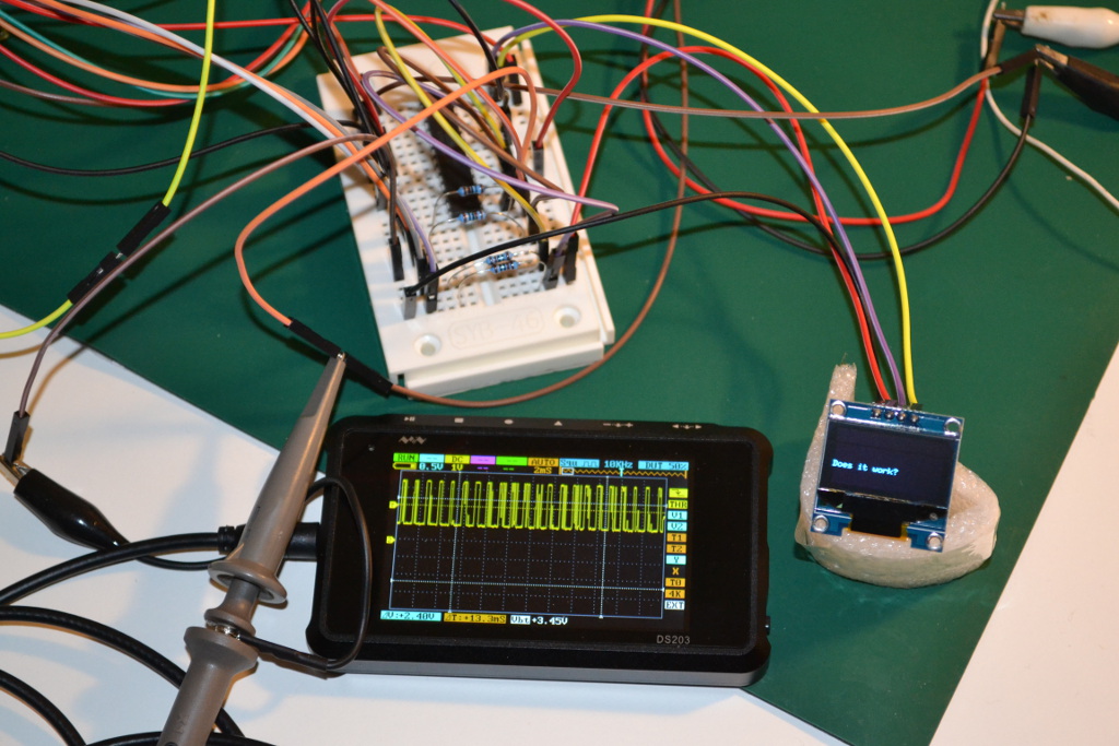
Final result. The (pretty bad) signal is from my RF433Mhz receiver. My RPi sends a string using a RF433 transmitter which is then received and decoded by an assembly routine I wrote for the ATMega328. The resulting string is then displayed instead of the standard ‘Hello world’ string. Admittedly currently the string is only correctly decoded once in several times due to noise on the wires.